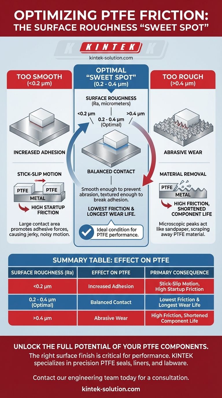
In short, there is a critical "sweet spot" for surface roughness. While it seems counterintuitive, a surface that is too smooth can increase friction through a phenomenon known as stick-slip. Conversely, a surface that is too rough will cause abrasive wear and also increase friction. The optimal performance of PTFE is achieved when the mating surface has a moderately polished finish.
The relationship between surface roughness and PTFE friction is not linear. Achieving the lowest friction and longest wear life requires engineering the mating surface to a specific roughness—neither too smooth nor too rough—to prevent both adhesion and abrasion.
Why Surface Finish is a Critical Design Parameter
Polytetrafluoroethylene (PTFE) is renowned for having one of the lowest coefficients of friction of any solid material. However, realizing this potential in a real-world application, such as a seal or bearing, depends heavily on the design of the entire system, especially the mating surface.
The Problem with an Ultra-Smooth Surface
When a mating surface is exceptionally smooth (e.g., a mirror-finish polish), the real area of contact with the PTFE can increase dramatically.
This large contact area promotes adhesive forces, which can lead to a stick-slip behavior. The components will "stick" until enough force builds up to break the adhesion, causing them to "slip" forward suddenly. This cycle results in jerky motion, noise, and an effectively higher coefficient of friction.
The Danger of a Rough Surface
If the mating surface is too rough, its microscopic peaks and valleys act like sandpaper against the much softer PTFE.
This causes abrasive wear, physically scraping away PTFE material from the component. This not only shortens the life of the part but also increases frictional resistance as the rough surface plows through the PTFE.
The Optimal "Sweet Spot" for Low Friction
The ideal condition for PTFE is a moderately polished metal surface that balances these two extremes.
A surface roughness, or Ra, of approximately 0.2 to 0.4 micrometers is considered optimal. This finish is smooth enough to prevent significant abrasive wear but has just enough microscopic texture to prevent the large-scale adhesion that causes stick-slip.
Understanding the Trade-offs
Specifying the surface finish for a component that will contact PTFE is an exercise in balancing competing failure modes. Your decision directly impacts both performance and longevity.
Friction vs. Wear Life
The primary trade-off is between low static friction and long-term wear resistance.
An extremely smooth surface might offer low sliding friction once motion starts, but it risks high startup friction and stick-slip. A rougher surface avoids stick-slip but guarantees high wear and a shortened operational life for the PTFE component. The optimal Ra range is the point where both of these negative effects are minimized.
The Influence of Other Factors
It is important to remember that surface finish is not the only variable at play.
Factors such as contact pressure, sliding velocity, and temperature also significantly influence the coefficient of friction. For example, higher pressures and lower velocities generally lead to a lower coefficient of friction for PTFE against a properly prepared surface like stainless steel.
How to Specify Your Mating Surface
When designing or troubleshooting a system with PTFE components, use the following guidelines for the mating surface finish.
- If your primary focus is minimizing stick-slip and startup torque: Avoid mirror-like polishes and target the recommended Ra range to break up adhesive forces.
- If your primary focus is maximizing the life of the seal or bearing: Avoid rough or machined surfaces that will cause rapid abrasive wear and ensure the finish is smooth and free of sharp peaks.
- If your primary focus is achieving optimal overall performance: Specify a surface finish with a roughness (Ra) between 0.2 and 0.4 micrometers to achieve the best balance of low friction and long wear life.
Controlling the mating surface finish is the key to unlocking the exceptional low-friction properties that make PTFE so valuable.
Summary Table:
| Surface Roughness (Ra) | Effect on PTFE | Primary Consequence |
|---|---|---|
| Too Smooth (<0.2 μm) | Increased Adhesion | Stick-Slip Motion, High Startup Friction |
| Optimal (0.2 - 0.4 μm) | Balanced Contact | Lowest Friction & Longest Wear Life |
| Too Rough (>0.4 μm) | Abrasive Wear | High Friction, Shortened Component Life |
Unlock the full potential of your PTFE components. The right surface finish is critical for performance. KINTEK specializes in precision PTFE seals, liners, and labware for semiconductor, medical, and industrial applications. Our experts can help you specify the optimal surface finish and provide custom fabrication from prototypes to high-volume orders to ensure low friction and long service life.
Contact our engineering team today for a consultation.
Visual Guide
Related Products
- Custom PTFE Measuring Cylinders for Advanced Scientific and Industrial Applications
- Corrosion Resistant White PTFE Solid Sampler Manual Sampling Tool Customizable Length
- Customizable 22ml PTFE Cup Deep Layer Sampler and Corrosion Resistant Cylinder with Handle
- High Temperature Resistant PTFE Solid Sampler Corrosion Resistant Non Leaching Reusable Biopharmaceutical White Powder Sampling Device
- High Purity Custom PTFE Solid Sampler for Laboratory Extraction and Chemical Analysis Polytetrafluoroethylene Sampling Probe with Customizable Length
People Also Ask
- What are some custom grades of PTFE and their compositions? Engineered for Wear, Strength, and Lubricity
- What does PTFE coating thickness refer to? The Key to Durability and Performance
- Why are Teflon rods preferred in the food and pharmaceutical sectors? Ensure Purity and Compliance
- What chemicals is Teflon resistant to? The Ultimate Guide to PTFE Chemical Inertness
- What colors are available for custom PTFE grades? Select the Right Color for Performance and Identification