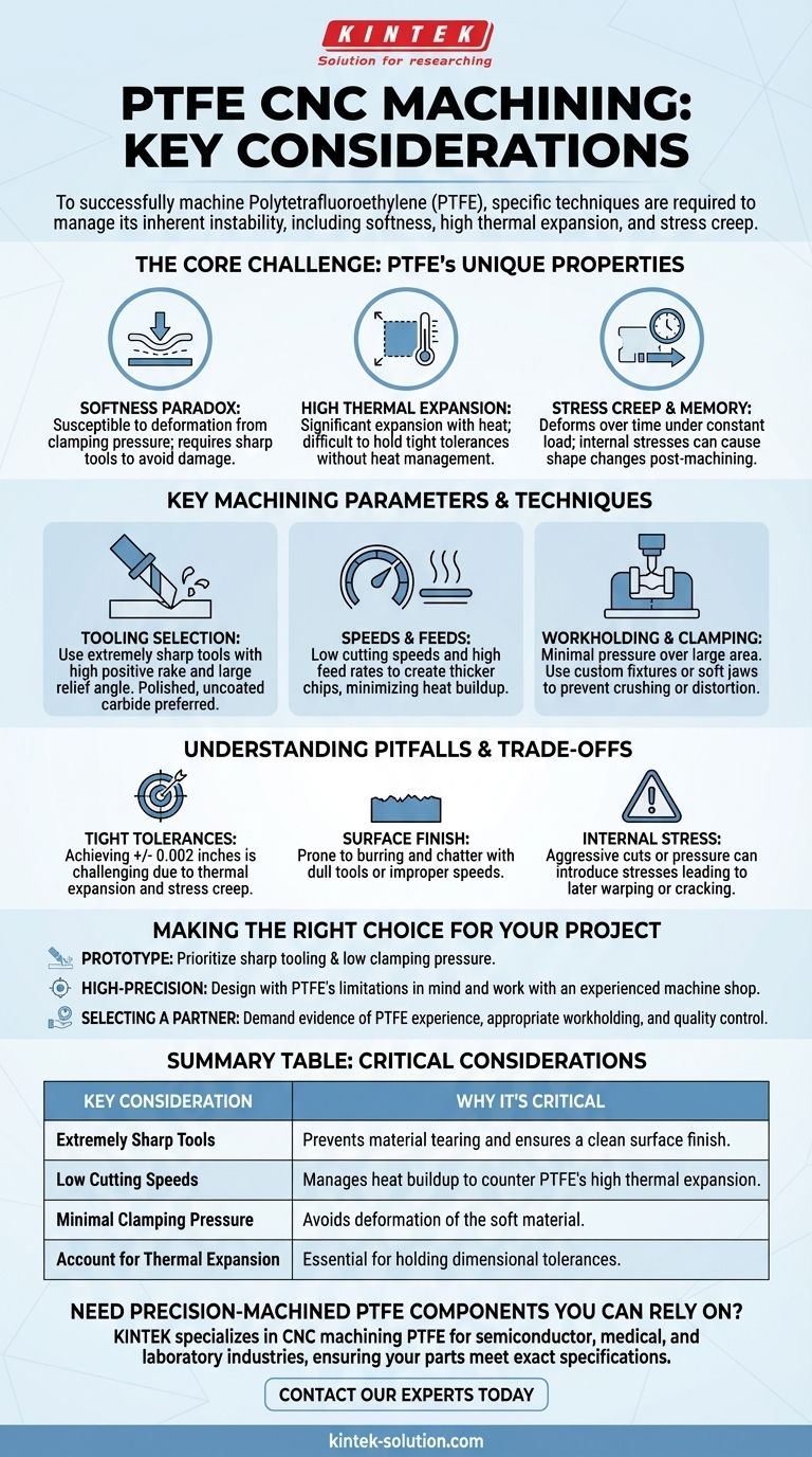
To successfully machine Polytetrafluoroethylene (PTFE), you must use extremely sharp tools, manage low cutting speeds to prevent heat buildup, use minimal clamping pressure to avoid deformation, and meticulously account for the material's high rate of thermal expansion. These considerations are not merely best practices; they are fundamental requirements for achieving any degree of dimensional accuracy with this unique material.
The central challenge in CNC machining PTFE is not its softness, which makes it easy to cut, but its inherent instability. Success depends entirely on techniques that accommodate its tendency to deform under pressure, expand with heat, and creep over time, rather than trying to force it into a rigid machining process.
The Core Challenge: PTFE's Unique Properties
Understanding why PTFE requires such specific handling is the first step toward mastering it. The material's primary benefits—low friction, chemical inertness—are directly linked to the properties that make it difficult to machine with precision.
The Softness Paradox
PTFE has a low Rockwell hardness, making it exceptionally easy to cut. However, this same softness means it is highly susceptible to deformation from clamping pressure and can be easily damaged by dull or chipped cutting tools, leading to a poor surface finish.
High Thermal Expansion
PTFE has one of the highest coefficients of thermal expansion among polymers. Even a small temperature increase from the cutting process can cause the material to expand significantly, making it nearly impossible to hold tight tolerances without careful heat management.
Stress Creep and Memory
This material is prone to stress creep, meaning it will slowly deform over time when under a constant load (like from a clamp or a press-fit). It also possesses a "memory," where internal stresses induced during machining can cause the part to change shape hours or even days later.
Key Machining Parameters and Techniques
To counteract these material properties, a specific set of operational parameters is required. These are non-negotiable for achieving a quality result.
Tooling Selection
The single most important factor is the sharpness of the cutting tool. Tools should have a high positive rake and a large relief angle. Polished, uncoated carbide tools are often preferred as they create less friction and heat.
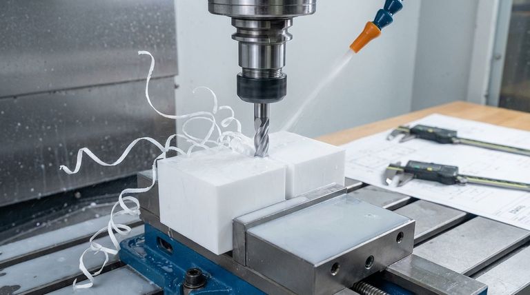
Speeds and Feeds
To manage thermal expansion, low cutting speeds and high feed rates are generally recommended. This approach creates a thicker chip that carries heat away from the workpiece, minimizing temperature buildup in the part itself.
Workholding and Clamping
Standard machine vises will easily crush or distort PTFE. Use minimal clamping pressure distributed over a large surface area. Custom fixtures or soft jaws are often necessary to securely hold the part without introducing stress or warping.
Understanding the Pitfalls and Trade-offs
Machining PTFE involves accepting certain limitations. Pushing the material beyond its capabilities is a common source of failure.
The Difficulty of Tight Tolerances
Achieving tolerances tighter than +/- 0.002 inches is extremely challenging and requires an expert machinist. The combination of thermal expansion and stress creep means the part's final dimension may differ from its dimension immediately after cutting.
Surface Finish Challenges
While easy to cut, PTFE is prone to burring and chatter. A poor finish is often a sign of a dull tool, excessive heat, or improper speeds and feeds. Post-processing techniques like shot peening or micro-polishing may be needed for critical surfaces.
Risk of Internal Stress
Aggressive cuts, excessive clamping pressure, or dull tooling can introduce internal stresses into the part. This stress can cause the component to warp or crack long after the machining is complete, leading to premature failure.
Making the Right Choice for Your Project
Your approach should be dictated by the specific requirements of your component.
- If your primary focus is a prototype or non-critical part: Prioritize the fundamentals of sharp tooling and low clamping pressure, as this will prevent the most common failures.
- If your primary focus is a high-precision component: You must design the part with PTFE's limitations in mind and work with a machine shop that has verifiable experience with this specific material.
- If your primary focus is selecting a machining partner: Demand evidence of their experience with PTFE, confirm they use appropriate workholding, and ask about their quality control process for managing thermal expansion.
Ultimately, successful PTFE machining is a matter of respecting the material's inherent nature rather than fighting it.
Summary Table:
| Key Consideration | Why It's Critical |
|---|---|
| Extremely Sharp Tools | Prevents material tearing and ensures a clean surface finish. |
| Low Cutting Speeds | Manages heat buildup to counter PTFE's high thermal expansion. |
| Minimal Clamping Pressure | Avoids deformation of the soft material. |
| Account for Thermal Expansion | Essential for holding dimensional tolerances. |
Need precision-machined PTFE components you can rely on?
At KINTEK, we specialize in CNC machining PTFE for the semiconductor, medical, and laboratory industries. Our expertise in managing material properties like thermal expansion and stress creep ensures your seals, liners, and custom labware meet exact specifications, from prototypes to high-volume production.
Contact our experts today to discuss your project and get a quote.
Visual Guide
Related Products
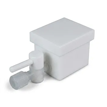
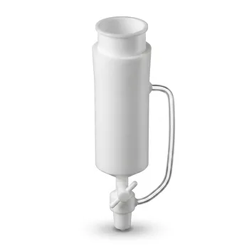
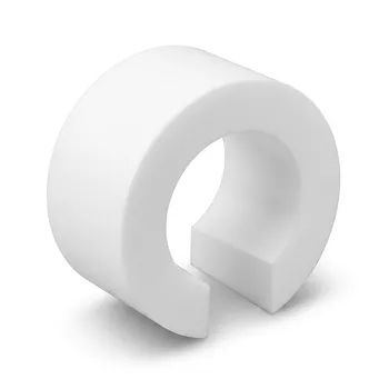
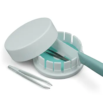
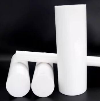
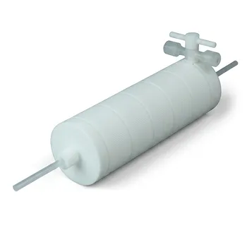
- Custom PTFE Laboratory Apparatus Corrosion Resistant Low Background Reaction Cells Precision CNC Fabrication
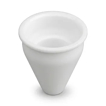
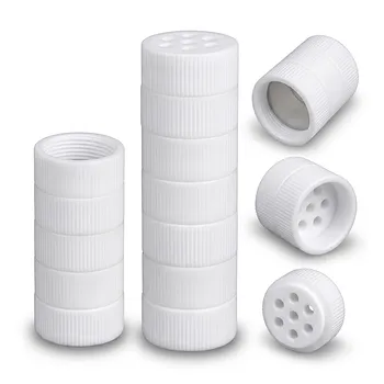
- Custom Machined PTFE Conical Sample Cell Corrosion Resistant Triangular Fluoropolymer Container for Trace Analysis
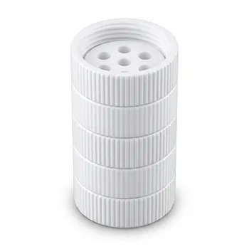
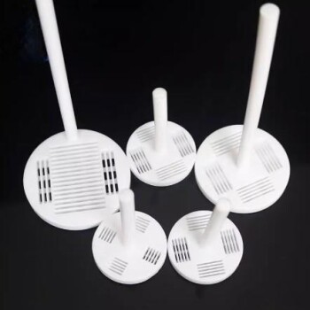
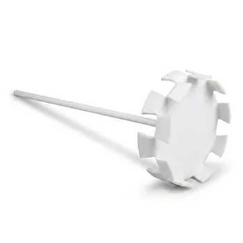
- High Temperature PTFE Reaction Sieve with Customizable Layers and Precision Pore Sizes for Threaded Sample Separation Devices
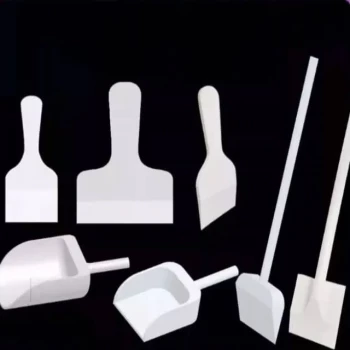
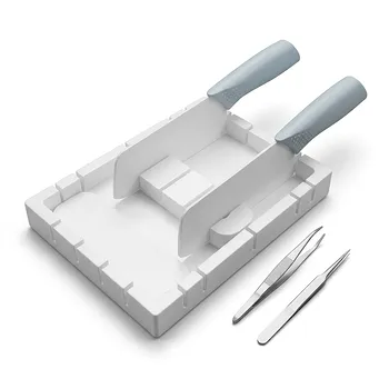
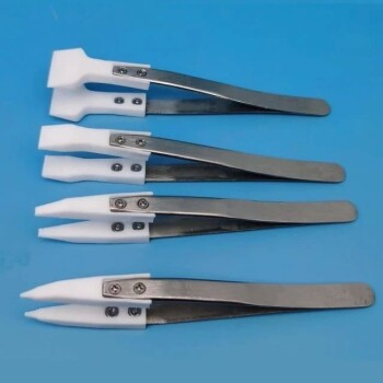
- Customizable PTFE Scrapers and Shovels for Demanding Applications
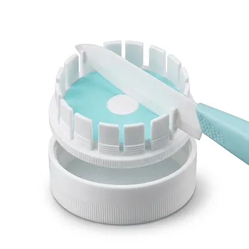
- Custom Machined Molded PTFE Teflon Parts Manufacturer for Laboratory ITO FTO Conductive Glass Cleaning Flower Basket
People Also Ask
- What are the primary fabrication methods for PTFE laboratory apparatus? Expert Insights into Fluoropolymer Engineering
- What are the primary chemical resistance properties of PTFE laboratory apparatus? Unmatched Purity and Inertness
- What are the mechanical and safety advantages of using PTFE apparatus in a laboratory? Enhance Safety & Durability
- What is the operational temperature range for PTFE laboratoryware? Mastering Thermal Limits from -200°C to +260°C
- How does PTFE compare to Polyethylene (PE) in terms of chemical and temperature resistance? Choose the Right Polymer for Extreme Conditions