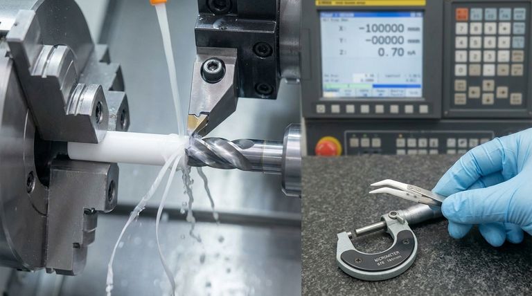
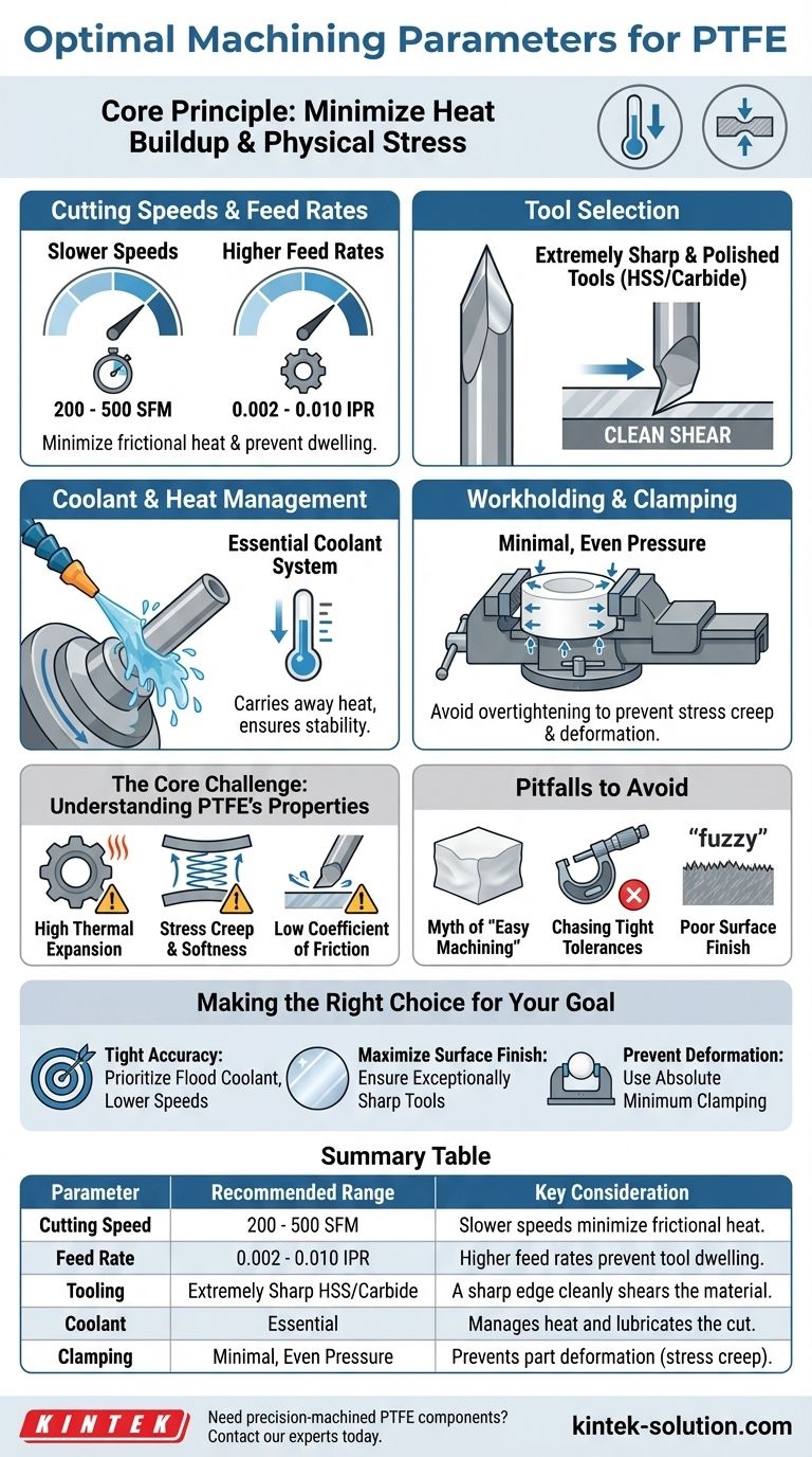
For optimal machining of PTFE, you should use slower cutting speeds between 200 and 500 SFM (surface feet per minute) and higher feed rates from 0.002 to 0.010 inches per revolution. The core principle is to minimize heat buildup and physical stress on the material, which requires extremely sharp tooling, the use of coolant, and minimal clamping pressure to prevent the part from deforming.
The central challenge in machining PTFE is not its softness, but its unique physical properties. Success depends entirely on managing its high thermal expansion and tendency to deform under pressure (stress creep), rather than treating it like a typical plastic or metal.
The Core Challenge: Working With PTFE's Nature
While PTFE's softness makes it seem easy to cut, achieving precision is difficult. The material's inherent properties create specific challenges that must be addressed proactively.
High Thermal Expansion
PTFE expands and contracts significantly with temperature changes. The friction from cutting generates heat, causing the material to grow during the machining process. If not managed, the part will be undersized once it cools to room temperature.
Stress Creep and Softness
The material is soft and will easily deform under pressure. Excessive clamping force will compress the workpiece, leading to inaccurate dimensions once the pressure is released. It can also "spring back" after a cutting tool passes, affecting the final surface finish and accuracy.
Low Coefficient of Friction
PTFE is famously slippery, which means a dull cutting edge will tend to push or plow the material rather than shearing it cleanly. This generates excess heat, introduces stress, and results in a poor-quality cut.
Recommended Machining Parameters and Techniques
To counteract PTFE's natural tendencies, a specific and deliberate approach is required. The goal is always to minimize heat and stress.
Cutting Speeds and Feed Rates
The recommended range is 200 to 500 SFM for cutting speed and 0.002 to 0.010 IPR (inches per revolution) for the feed rate. Slower speeds reduce frictional heat, while higher feed rates help the tool remove material efficiently without dwelling and imparting unnecessary heat.
Tool Selection
Use extremely sharp and polished cutting tools. Both High-Speed Steel (HSS) and carbide tools are effective, but the sharpness of the cutting edge is the most critical factor. A sharp edge cleanly shears the material, while a dull one will cause it to deform and tear.
Coolant and Heat Management
A coolant system is essential for any precision work. The coolant serves two primary functions: it lubricates the cut and, more importantly, it carries away heat, ensuring the workpiece remains dimensionally stable throughout the operation.
Workholding and Clamping
Apply minimal and evenly distributed clamping pressure. Avoid overtightening vises or chucks. Custom fixtures that support the workpiece without compressing it are ideal for holding tight tolerances.
Understanding the Pitfalls to Avoid
Many common machining practices will produce poor results with PTFE. Understanding these pitfalls is key to avoiding costly mistakes and material waste.
The Myth of "Easy Machining"
The softness of PTFE is deceptive. While material removal is easy, achieving dimensional stability and a good surface finish is a significant challenge. Do not approach it with the same high-speed techniques used for more rigid materials.
Chasing Tight Tolerances
Holding very tight tolerances on PTFE parts is difficult and requires a controlled environment and process. The operator must constantly monitor for thermal expansion and tool wear, making adjustments as needed.
Poor Surface Finish
A rough or fuzzy surface finish is a clear sign that something is wrong. The most common causes are a dull cutting tool, excessive heat generation, or vibration and chatter from an unstable setup.
Making the Right Choice for Your Goal
Your specific objective will determine which parameters you should prioritize.
- If your primary focus is achieving tight dimensional accuracy: Prioritize aggressive thermal management by using a flood coolant system and keeping cutting speeds in the lower end of the recommended range.
- If your primary focus is maximizing surface finish: Ensure your cutting tools are exceptionally sharp with a polished face to prevent material from sticking and tearing.
- If your primary focus is preventing part deformation: Use the absolute minimum clamping pressure required to hold the part securely, and ensure the force is distributed over a wide surface area.
Mastering PTFE machining comes from respecting the material's properties and adapting your process to accommodate them.
Summary Table:
| Parameter | Recommended Range | Key Consideration |
|---|---|---|
| Cutting Speed | 200 - 500 SFM | Slower speeds minimize frictional heat. |
| Feed Rate | 0.002 - 0.010 IPR | Higher feed rates prevent tool dwelling. |
| Tooling | Extremely Sharp HSS/Carbide | A sharp edge cleanly shears the material. |
| Coolant | Essential | Manages heat and lubricates the cut. |
| Clamping | Minimal, Even Pressure | Prevents part deformation (stress creep). |
Need precision-machined PTFE components that hold their shape and dimensions?
At KINTEK, we specialize in machining PTFE for the semiconductor, medical, and laboratory industries. Our expertise in managing thermal expansion and stress creep ensures your seals, liners, and custom labware are produced to exact specifications, from prototypes to high-volume orders.
Contact our experts today to discuss your project and get a quote!
Visual Guide
Related Products
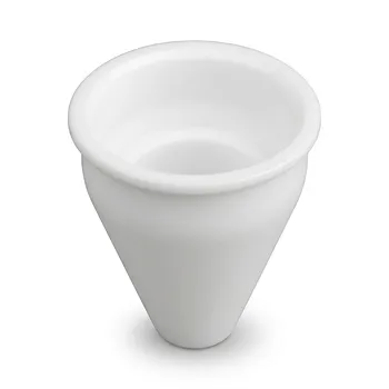
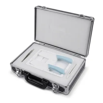
- Custom Machined PTFE Conical Sample Cell Corrosion Resistant Triangular Fluoropolymer Container for Trace Analysis
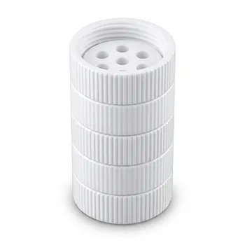
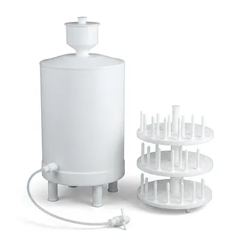
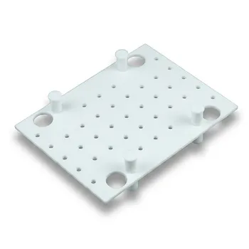
- High Temperature PTFE Reaction Sieve with Customizable Layers and Precision Pore Sizes for Threaded Sample Separation Devices
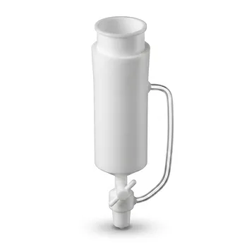
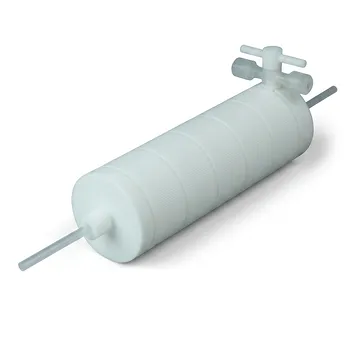
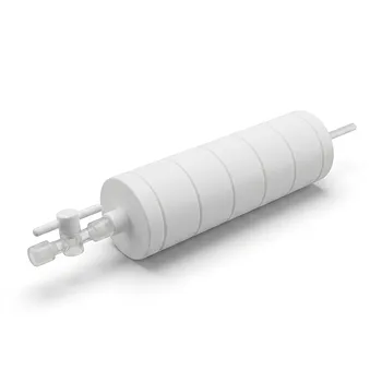
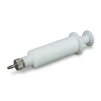
- Custom PTFE Constant Pressure Separatory Funnel Corrosion Resistant Low Background Labware for PFA Flasks
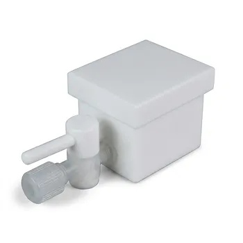
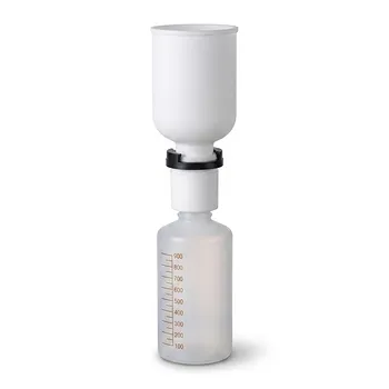
- Custom PTFE Laboratory Apparatus Corrosion Resistant Low Background Reaction Cells Precision CNC Fabrication
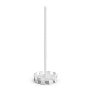
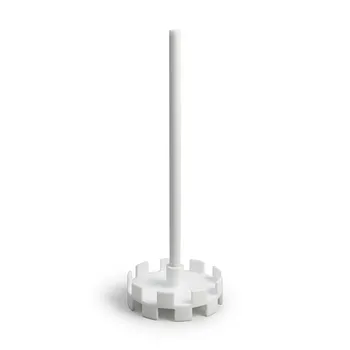
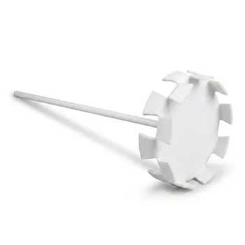
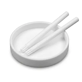
- Custom PTFE Dispersing Disc and Stirring Rod for Chemical Processing and Laboratory Mixing
People Also Ask
- What are the main advantages of using PTFE for custom parts? Solve Complex Engineering Challenges
- Can PTFE parts be customized according to specific requirements? Achieve Precision Custom PTFE Components
- What makes machined PTFE suitable for industrial applications? Unmatched Performance in Extreme Conditions
- How do Polytetrafluoroethylene (PTFE) containers perform regarding gas permeation? Expert Insights on Solvent Absorption
- How are PTFE laboratory containers and apparatus typically manufactured? Inside the Precision Machining Process