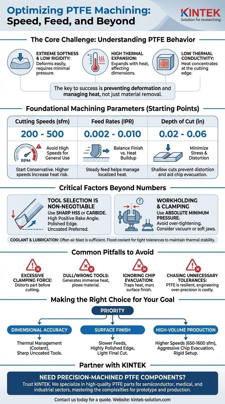
For machining Polytetrafluoroethylene (PTFE), the optimal parameters are a cutting speed between 200 to 500 surface feet per minute (sfm) and a feed rate from 0.002 to 0.010 inches per revolution (IPR). However, these numbers are only a starting point. Successfully machining PTFE depends less on specific speeds and feeds and more on managing the material's unique properties, such as its softness, low thermal conductivity, and high thermal expansion.
The central challenge in machining PTFE is not material removal, but preventing deformation and managing heat. Success hinges on using exceptionally sharp tools with high rake angles and applying minimal cutting and clamping pressure to maintain dimensional stability.

The Core Challenge: Understanding PTFE's Behavior
PTFE, commonly known as Teflon, is unlike metals or even other plastics. Its properties demand a specific approach to machining.
Extreme Softness and Low Rigidity
PTFE is an incredibly soft material that deforms easily under pressure. Any excessive force from clamping or cutting will cause the workpiece to distort, making it impossible to hold tight tolerances.
This softness also means the material offers little resistance, which can lead to vibration or "chatter" if the setup is not rigid and the cutting tools are not sharp.
High Thermal Expansion
PTFE has one of the highest coefficients of thermal expansion among polymers. Even a small increase in temperature from cutting friction will cause the material to expand significantly, throwing dimensions off.
Once the part cools, it will contract, resulting in a final part that is undersized and out of tolerance.
Low Thermal Conductivity
Unlike metals that dissipate heat throughout the workpiece, PTFE is an insulator. Heat generated at the cutting edge stays concentrated there.
This localized heat can cause the material to soften, become gummy, and build up on the tool edge, leading to a poor surface finish and further cutting problems.
Foundational Machining Parameters
While technique is paramount, having a solid baseline for your machine settings is the essential first step. Always start conservatively and adjust based on the results.
Cutting Speeds: A Balancing Act
A safe and effective starting range for cutting speed is 200 to 500 sfm (approximately 60 to 150 m/min).
Some sources suggest much higher speeds are possible (up to 1600 sfm / 500 m/min). While PTFE's low friction can accommodate this, it dramatically increases the risk of heat-related problems and requires excellent chip evacuation. For general purposes, stick to the lower range.
Feed Rates: Controlling Heat and Finish
A feed rate of 0.002 to 0.010 IPR (approximately 0.05 to 0.25 mm/rev) is the recommended starting point.
There is a critical trade-off here. Slower feeds can improve surface finish, but they also increase the time the tool spends generating friction in one area. A slightly higher, steady feed rate can help the tool move on before excessive localized heat builds up.
Depth of Cut: Minimizing Stress
Keep your depth of cut shallow, generally in the range of 0.02 to 0.06 inches (0.5 to 1.5 mm).
Deeper cuts impart more stress into the flexible material, increasing the likelihood of distortion and making it difficult for chips to evacuate properly.
Critical Factors Beyond Speed and Feed
Your choice of tooling and your setup have a greater impact on the final result than the exact numbers you dial into the machine.
Tool Selection is Non-Negotiable
The single most important factor is the cutting tool. Use High-Speed Steel (HSS) or carbide tools with a very sharp, polished cutting edge.
Tools must have a high positive rake angle. This creates a shearing action that slices the material cleanly rather than pushing or tearing it. Uncoated tools are often preferred, as some coatings can increase friction and heat buildup.
The Cooling and Lubrication Debate
Coolant is not always necessary and can be a source of contamination. For many applications, a simple compressed air blast is sufficient to clear chips away from the cutting zone effectively.
However, for jobs requiring very tight tolerances, a flood coolant can be invaluable for thermal stability. It carries heat away before the part can expand, preserving dimensional accuracy.
Workholding and Clamping Pressure
Use the absolute minimum clamping pressure required to hold the workpiece securely. Over-tightening a vise is the most common cause of deformed parts.
For delicate or complex geometries, consider using vacuum fixtures or soft jaws to distribute clamping force and provide stability without crushing the material.
Common Pitfalls to Avoid
Mistakes in machining PTFE are often related to treating it like a more rigid material.
Applying Excessive Clamping Force
This is the number one error. It will distort the part before you even make the first cut, guaranteeing an inaccurate result.
Using Dull or Incorrectly Ground Tools
A tool that is not razor-sharp or lacks a high positive rake will plow through the material instead of cutting it. This generates immense heat, causes material to build up on the tool, and results in a terrible surface finish.
Ignoring Chip Evacuation
PTFE produces long, stringy chips that can wrap around the tool and workpiece. This traps heat and can mar the surface finish. An air blast or proper coolant flow is essential to clear these chips away continuously.
Chasing Unnecessary Tolerances
PTFE is a resilient material. After machining, it can often conform to its mating parts. Unless the application is highly critical, engineering for extremely tight tolerances may be an unnecessary and costly effort.
Making the Right Choice for Your Goal
Adjust your approach based on the most critical outcome for your specific part.
- If your primary focus is dimensional accuracy: Prioritize thermal management with a consistent coolant flow and use sharp, uncoated tools to minimize friction.
- If your primary focus is surface finish: Use slower feed rates for a finer cut, ensure your tool has a highly polished edge, and take a light final depth of cut.
- If your primary focus is high-volume production: Explore higher cutting speeds (650-1600 sfm), but pair this with aggressive chip evacuation and a rigid setup to maintain control.
Ultimately, mastering PTFE machining comes from respecting the material's unique properties and adjusting your technique accordingly.
Summary Table:
| Parameter | Recommended Starting Range | Key Consideration |
|---|---|---|
| Cutting Speed | 200 - 500 sfm (60-150 m/min) | Higher speeds increase heat risk; balance with chip evacuation. |
| Feed Rate | 0.002 - 0.010 IPR (0.05-0.25 mm/rev) | A steady feed helps manage localized heat buildup. |
| Depth of Cut | 0.02 - 0.06 in (0.5-1.5 mm) | Shallow cuts minimize stress and prevent part distortion. |
| Tool Material | Sharp HSS or Carbide | A high positive rake angle and polished edge are non-negotiable. |
Need Precision-Machined PTFE Components?
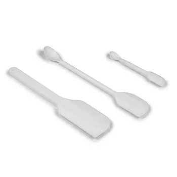
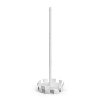
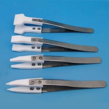
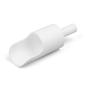
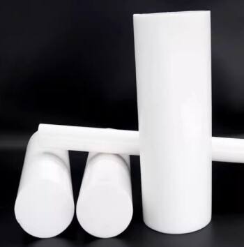
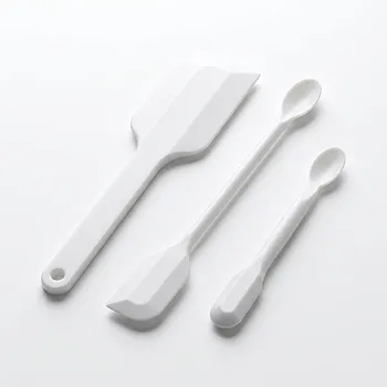
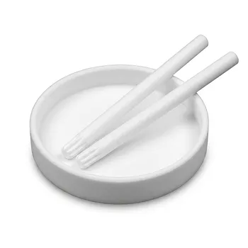
At KINTEK, we specialize in manufacturing high-quality PTFE components—from seals and liners to custom labware—for the semiconductor, medical, and industrial sectors. We understand the precise techniques required to machine PTFE without compromising dimensional stability or surface finish.
Let us handle the complexity for you. Our expertise ensures your parts are produced to the highest standards, whether you need prototypes or high-volume production.
Contact us today to discuss your project and get a quote!
Visual Guide
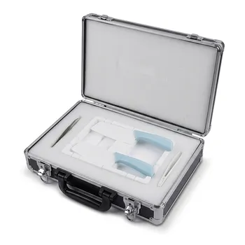
Related Products
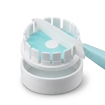
- High Purity PTFE Filter Membrane Cutter with Ceramic Blade for PM2.5 Analysis and Customizable Laboratory Filter Paper Splitter
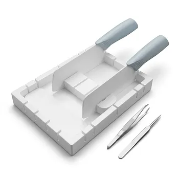
- High Purity PTFE Square Membrane Cutter and Filter Aliquot Device for Trace Analysis and Cleanroom Laboratory Applications
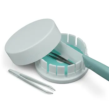
- High Purity PTFE Circular Filter Membrane Cutter with Ceramic Blade for Trace Analysis and CDC Laboratory Sample Preparation
- High Purity PTFE Square Membrane Cutter Equipartition Device for Trace Analysis and Disease Control Centers Clean Non Stick No Leaching
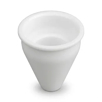
- Custom Machined PTFE Conical Sample Cell Corrosion Resistant Triangular Fluoropolymer Container for Trace Analysis
People Also Ask
- Which chemicals are fully compatible with PTFE filters? Discover Unmatched Chemical Resistance
- What is the thermal stability range for PTFE filter membranes? Master Extremes from -200°C to +260°C
- How does the hydrophobicity of PTFE filters benefit their use? Ensure Uninterrupted Gas Flow and Solvent Filtration
- What sizes and pore options are available for PTFE filters? Choose the Right Filter for Your Application
- What steps are involved in selecting the proper PTFE filter? A 4-Step Guide to Optimal Filtration