The fundamental challenge in machining Polytetrafluoroethylene (PTFE) is its paradoxical nature. While famously soft and easy to cut, its properties cause surprisingly rapid tool wear, especially when approached with conventional machining parameters. This accelerated wear is primarily driven by improper tool geometry, incorrect feed rates, and excessive heat buildup, leading to dimensional inaccuracies and increased operational costs.
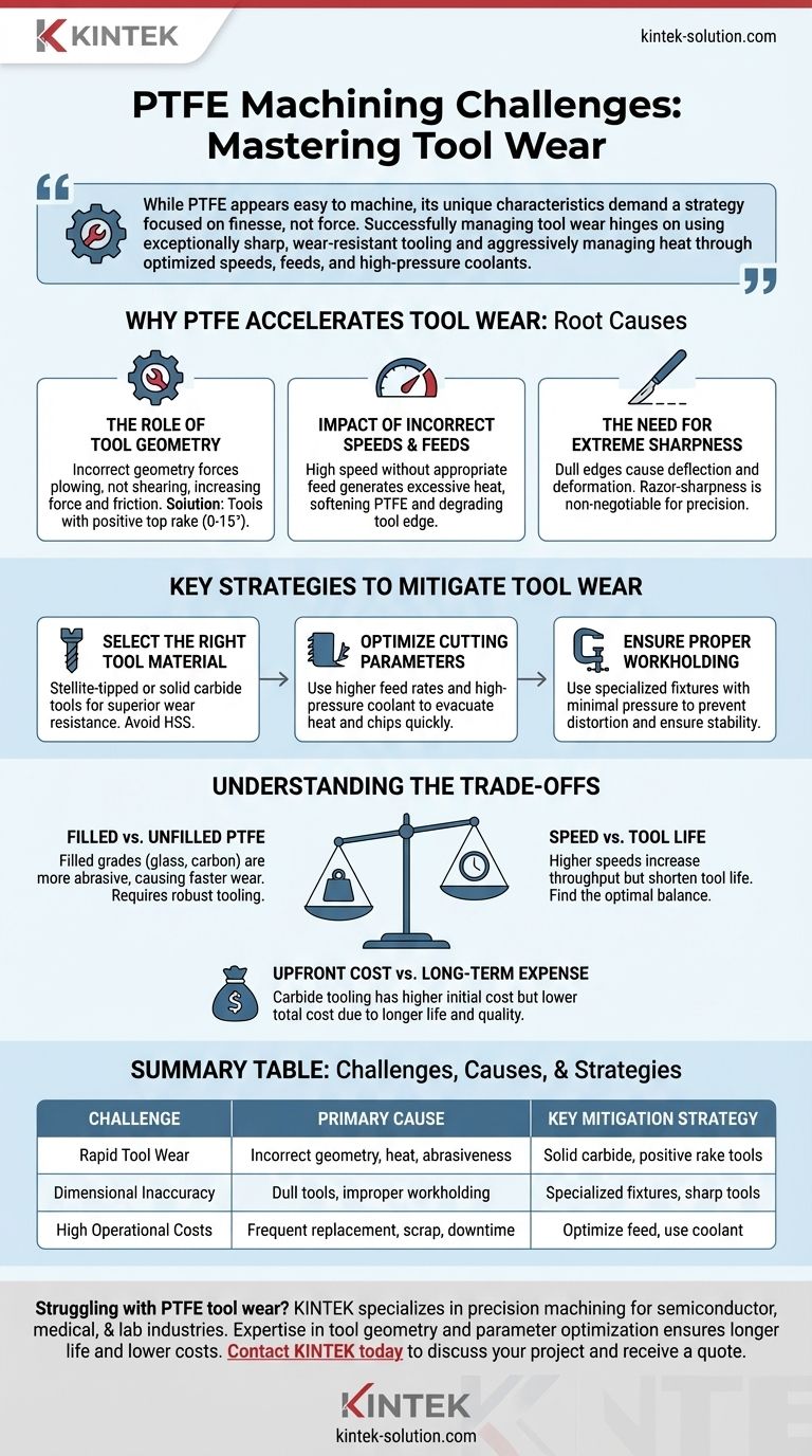
While PTFE appears easy to machine, its unique characteristics demand a strategy focused on finesse, not force. Successfully managing tool wear hinges on using exceptionally sharp, wear-resistant tooling and aggressively managing heat through optimized speeds, feeds, and high-pressure coolants.
Why PTFE Accelerates Tool Wear
Understanding the root causes of tool wear is the first step toward mitigating it. PTFE interacts with cutting tools in ways that differ significantly from metals or even other polymers.
The Role of Tool Geometry
An incorrect tool geometry forces the tool to plow through or deform the material rather than shearing it cleanly. This dramatically increases cutting forces and friction.
Tools with a positive top rake (between 0 and 15 degrees) are essential. This geometry creates a sharper cutting edge that reduces pressure, minimizes heat buildup, and promotes a smoother cutting action.
The Impact of Incorrect Speeds and Feeds
While it seems counterintuitive for a soft material, high speeds can be detrimental if not paired with an appropriate feed rate.
Letting a tool spin too fast without advancing it quickly enough generates excessive frictional heat. This heat can soften the PTFE, causing it to become gummy, and can also degrade the cutting edge of the tool itself, accelerating wear.
The Need for Extreme Sharpness
A dull cutting edge, even a microscopic one, will not cut PTFE effectively. Instead, it will cause deflection and material deformation.
Maintaining a razor-sharp edge is non-negotiable. Regular inspection and resharpening are critical to maintaining performance and preventing parts from going out of tolerance.
Key Strategies to Mitigate Tool Wear
Fortunately, these challenges can be overcome with a methodical approach that prioritizes the right tools and techniques.
Select the Right Tool Material
Standard high-speed steel (HSS) tools will wear down very quickly.
For any production work, Stellite-tipped or solid carbide tools are the ideal choice. Their superior hardness and wear resistance provide significantly longer life and help maintain a sharp cutting edge for longer periods.
Optimize Your Cutting Parameters
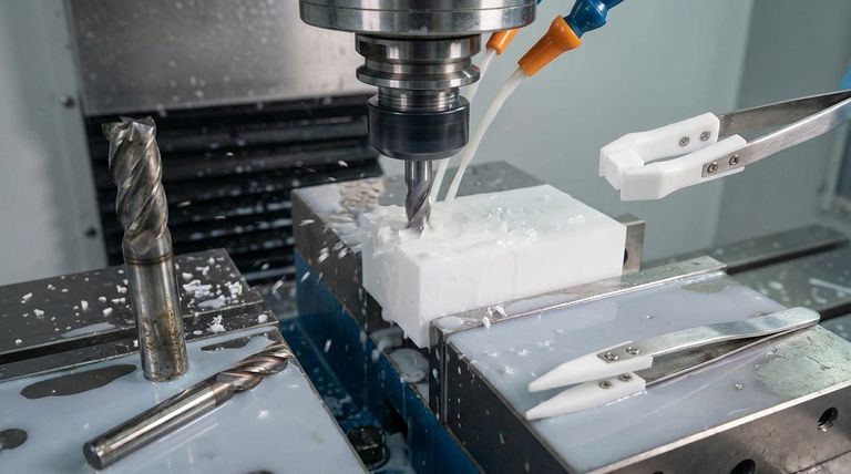
The goal is to cut the material and evacuate the chip as quickly as possible to prevent heat from building up in the tool or workpiece.
Using a higher feed rate in conjunction with appropriate speeds helps achieve this. Additionally, employing a high-pressure coolant is highly effective at reducing friction and clearing chips from the cutting zone.
Ensure Proper Workholding
PTFE's softness makes it prone to distortion under pressure. Over-tightening a vise or clamp will ruin the part's dimensional accuracy.
Use specialized fixtures designed for soft materials that provide broad support with minimal clamping pressure. This prevents warping and ensures the part remains stable during machining.
Understanding the Trade-offs
Making the right decision often involves balancing competing factors. There is no single "perfect" setup for every PTFE application.
Filled vs. Unfilled PTFE
Filled grades of PTFE (e.g., glass or carbon-filled) offer superior mechanical properties but are significantly more abrasive. Machining these materials will cause much faster tool wear than unfilled PTFE, requiring even more robust tooling like carbide and potentially slower speeds.
Speed vs. Tool Life
Pushing for maximum cutting speed to increase throughput will almost always result in a shorter tool life. It is critical to find the optimal balance where parts are produced efficiently without causing premature tool failure and costly downtime.
Upfront Tooling Cost vs. Long-Term Expense
Carbide tooling represents a higher initial investment than HSS. However, this cost is quickly offset by longer tool life, reduced scrap rates, and more consistent part quality, making it the more economical choice for anything beyond a one-off prototype.
Making the Right Choice for Your Goal
Your specific objective should guide your machining strategy. Use the following points as a starting point for optimizing your process.
- If your primary focus is maximum tool longevity: Prioritize wear-resistant solid carbide tooling with a positive rake and use high-pressure coolant consistently.
- If your primary focus is achieving the tightest tolerances: Emphasize specialized fixturing with minimal clamping pressure and ensure your tools are exceptionally sharp at all times.
- If your primary focus is high-volume production: Invest in optimized feed rates that evacuate heat quickly and implement a strict, regular tool resharpening or replacement schedule.
By treating PTFE as a unique material requiring precision and specific techniques, you can overcome its challenges and achieve consistent, high-quality results.
Summary Table:
| Challenge | Primary Cause | Key Mitigation Strategy |
|---|---|---|
| Rapid Tool Wear | Incorrect geometry, heat buildup, material abrasiveness | Use solid carbide tools with a positive rake angle |
| Dimensional Inaccuracy | Dull tools, improper workholding, part deformation | Employ specialized fixtures and maintain extreme tool sharpness |
| High Operational Costs | Frequent tool replacement, scrap parts, downtime | Optimize feed rates and use high-pressure coolant |
Struggling with PTFE tool wear and inconsistent parts? KINTEK specializes in precision PTFE machining for the semiconductor, medical, and laboratory industries. Our expertise in selecting the right tool geometry and optimizing cutting parameters ensures longer tool life, tighter tolerances, and lower costs for your custom PTFE components—from prototypes to high-volume production. Contact KINTEK today to discuss your project and receive a quote.
Visual Guide
Related Products
- Custom PTFE Scraper Shovel and Sampling Spoon Dual Use Corrosion Resistant Low Background White Fluoropolymer Tool
- Custom PTFE Laboratory Apparatus Corrosion Resistant Low Background Reaction Cells Precision CNC Fabrication
- Custom PTFE Sleeves and Hollow Rods for Advanced Applications
- Custom PTFE Double Headed Lab Spatula Chemical Resistant Non Stick Pharmaceutical Grade Fluoropolymer Sampling Tool
- Corrosion Resistant PTFE Sampling Spoon Spatula High Purity Low Background Food Grade Pharmaceutical Research Laboratory Tool
People Also Ask
- Why are PTFE shovels considered biocompatible? Ensure Sample Purity and Safety
- Why are PTFE shovels considered cost-effective? Maximize ROI with Superior Durability
- What are the advantages of PTFE shovels in terms of chemical resistance? Unmatched Inertness for Handling Corrosives
- How does the ergonomic design of PTFE shovels benefit users? Reduce Strain and Boost Lab Efficiency
- What are the key properties that make PTFE shovels ideal for laboratory use? Ensure Sample Integrity with Chemically Inert Tools