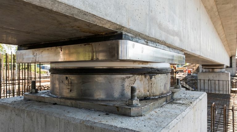
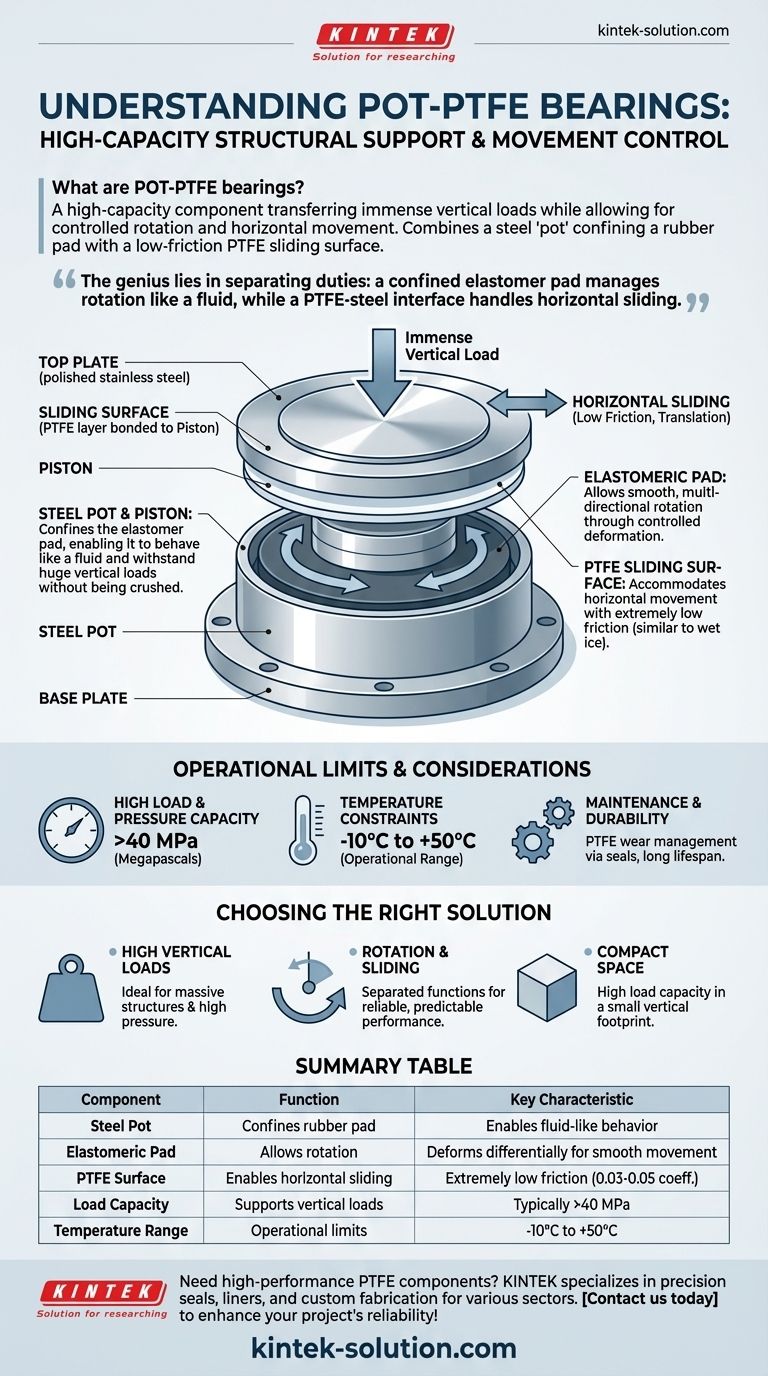
In essence, a POT-PTFE bearing is a high-capacity structural component designed to safely transfer immense vertical loads while simultaneously allowing for controlled rotation and horizontal movement. It achieves this by combining a steel "pot" that confines a rubber pad with a low-friction PTFE sliding surface, making it a critical element in large structures like bridges and heavy buildings.
The genius of the POT-PTFE bearing lies in its separation of duties: a confined elastomer pad manages rotation like a fluid, while a distinct PTFE-steel interface handles horizontal sliding. This allows the bearing to manage massive, multi-directional forces in a highly compact and predictable manner.
The Core Problem: Movement in Massive Structures
All large structures move. Forces from temperature changes, wind, traffic, and even seismic activity cause them to expand, contract, and shift. A structural bearing is the critical interface that must manage these movements while safely transferring the structure's immense weight to the foundation.
The Role of the Steel "Pot" and Piston
The foundational component is a shallow steel cylinder, or pot. Inside this pot sits a thin elastomeric (rubber) pad and a steel piston that fits snugly inside.
The pot's primary job is to confine the rubber pad. By preventing the pad from bulging outwards under pressure, the steel pot forces it to behave like a fluid, enabling it to withstand enormous vertical loads without being crushed.
The Elastomeric Pad: The Engine of Rotation
The elastomeric pad is the component that allows for rotation. When the structure above tilts, it applies uneven pressure on the piston.
This differential compression squashes one side of the confined rubber pad more than the other. This controlled deformation of the elastomer provides the smooth, multi-directional rotation the structure needs. The rotational capacity is typically limited to around 0.025 radians.
The PTFE Sliding Surface: Enabling Translation
To accommodate horizontal movement (translation), a layer of Polytetrafluoroethylene (PTFE) is bonded to the top of the piston. This PTFE surface slides against a polished stainless steel plate attached to the upper part of the bearing assembly.
PTFE is known for its extremely low coefficient of friction, similar to wet ice on wet ice. This property allows the upper and lower plates of the bearing to slide past each other with minimal resistance, accommodating thermal expansion and other horizontal forces.
Understanding the Operational Limits
While robust, POT-PTFE bearings are not without their constraints. Understanding these limits is critical for proper specification in any project.
Load and Pressure Capacity
These bearings are designed for high-pressure applications, often exceeding 40 MPa (megapascals). The exact capacity, however, can depend on the specific fillers and materials used in the PTFE and elastomeric components.
Temperature Constraints
The materials used in standard POT-PTFE bearings give them a defined operational temperature range, typically from -10°C to +50°C. Use outside of this range can compromise the performance of the elastomer and PTFE, requiring special design considerations.
Maintenance and Durability
The PTFE surface, while durable, can wear over time. The design often incorporates spring-energized seals or other mechanisms to maintain a tight fit, prevent contamination, and compensate for gradual wear over the structure's lifespan.
Making the Right Choice for Your Goal
Selecting the correct bearing is a matter of matching its capabilities to the specific demands of the structure.
- If your primary focus is supporting extremely high vertical loads: The confined elastomer design makes POT-PTFE bearings an excellent choice for massive structures where pressure is a primary concern.
- If your design requires both rotation and horizontal sliding: This bearing's ability to separate these two functions into different components provides highly reliable and predictable performance.
- If you are working within a compact space: POT-PTFE bearings offer very high load capacity in a relatively small vertical footprint compared to other bearing types.
By understanding how each component contributes to the whole, you can confidently specify the right solution for managing the dynamic forces acting on your structure.
Summary Table:
| Component | Function | Key Characteristic |
|---|---|---|
| Steel Pot | Confines rubber pad | Enables fluid-like behavior under pressure |
| Elastomeric Pad | Allows rotation | Deforms differentially for smooth movement |
| PTFE Surface | Enables horizontal sliding | Extremely low friction (0.03-0.05 coefficient) |
| Load Capacity | Supports vertical loads | Typically >40 MPa |
| Temperature Range | Operational limits | -10°C to +50°C |
Need high-performance PTFE components for your structural or industrial applications? KINTEK specializes in manufacturing precision PTFE seals, liners, and custom components for the semiconductor, medical, laboratory, and industrial sectors. Our expertise in custom fabrication—from prototypes to high-volume orders—ensures you get components that meet exact specifications for durability and performance. Contact us today to discuss how our PTFE solutions can enhance your project's reliability and efficiency!
Visual Guide
Related Products
- PTFE Silicon Wafer Holder for Acid Etching and Cleaning Process 2 4 6 8 Inch Customizable High Temperature Resistant
- Custom PTFE Laboratory Cleaning Basket Carrier High Purity Acid Base Resistant Wafer Holder Low Background Contamination Free Chemical Bath Rack
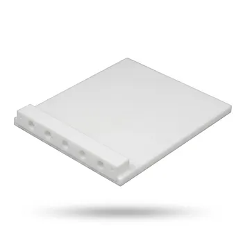
- Customizable PTFE Heat Insulation Plate High Temperature Corrosion Resistant Laboratory Support Layered Multi Tier Stand
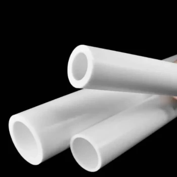
- Customizable PTFE Rods for Advanced Industrial Applications
- Custom PTFE Acid Resistant Support Rack for PFA Hydrogen Absorption Systems Multi Hole Configurations
People Also Ask
- What are some specialized Teflon bearing products? A Guide to Material Systems and Forms
- How are Teflon bearings manufactured? A Guide to Machining, Molding, and Coating
- How do the chemical properties of PTFE benefit the performance of electrode holders in battery testing? Ensure Pure Data
- What are some applications of Teflon in bearing technology? Achieve Maintenance-Free, Low-Friction Performance
- What is the purpose of PTFE etching? Unlock Bondable Surfaces for Your Components